Location of Surface Texture Symbols. Specify in inches or millimeters.
The Basics Of Surface Finish Gd T Basics
Set the attributes and values for the symbol in the Surface Texture dialog box and click OK.
. Symbols that indicate the surface texture of machined and structural parts are used in industrial diagrams. Engineering drawing abbreviations and symbols. Optional Select a symbol preset and modify as needed.
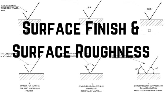
These symbols except a and f are provided when they are needed. The surface finish can be said as the surface texture or surface topography. Roughness value in micrometers preceded by parameter symbol.
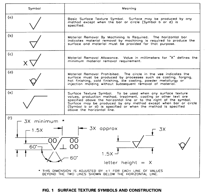
The American Society of Mechanical Engineers ASME has published the Y1436M Surface Texture Symbols standard which illustrates the proper specification and use of surface. Use these geometric dimensioning and tolerancing GDT shapes to create annotated mechanical drawings. Under ISO 1302 a finish range should be indicated as e in Fig.
The symbol is described in ASME Y1436M Surface texture symbols. Based on roughness deviations. On the ribbon click Annotate tab Symbols panel Surface.
Horizontal bar added to basic symbol. Surface finish a subjective term. Ra Rz in most cases.
Root-mean-square RMS the square root of. The surface finish is an overall measure of these three Characteristics. 43 Roughness Average Ra The principal parameter specified for roughness is the roughness average R defined in ASME B461.
Understanding surface roughness symbols. The mean of the squared deviation over the. When we try to measure a surface finish the methods fall into three categories.
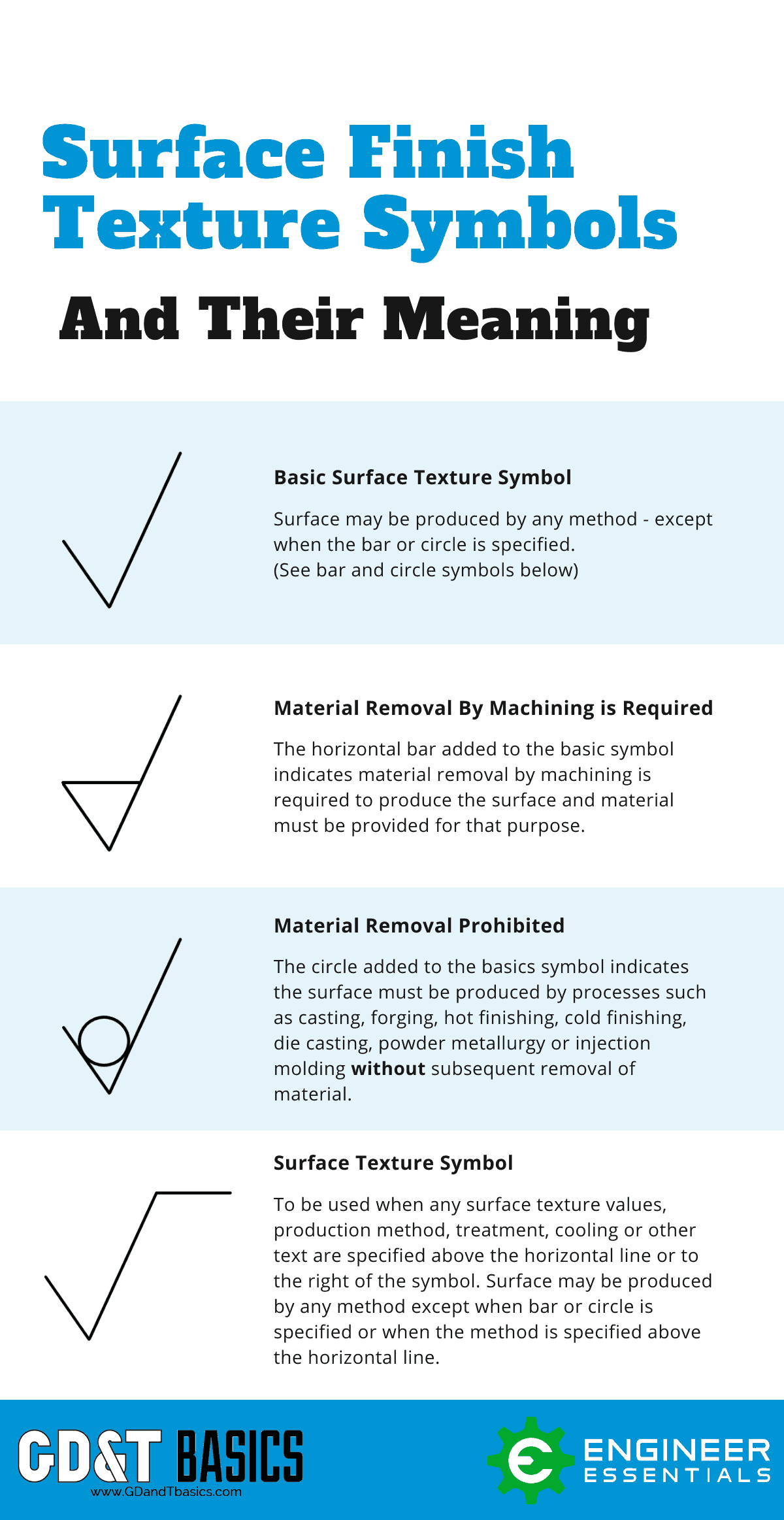
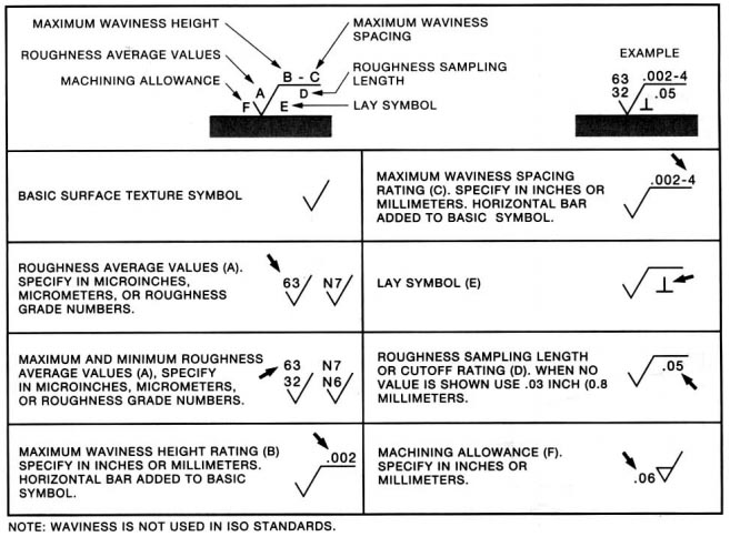
There are three surface roughness symbols see figure below indicating the surface a required material removal b. Example 63 32 002-4 05 002-4 05 06 60 63 002 lay symbol e roughness sampling length or cutoff rating d. When no value is shown use 03 inch 08 millimeters.
Ra is average roughness and its under-estimates surface height variations. Rz is mean roughness depth and it approximates the size of the most severe surface height variations. Symbol for surface texture all component surfaces.
The surface finish symbols used in engineering drawings are defined by technical standards such as ISO ANSI or AS Australian standard. Rp max height profile Rv max profile valley depth Rz max height of the profile Rc mean height of profile Rt total height of the profile Ra arithmetic mean deviation of the profile Rq root mean square deviation of the profile Rsk skewness of the profile Rku kurtosis of the profile RSm mean width of the profile. If your machine shop doesnt understand the symbol you should run away fast.
A surface roughness value cut-off value or reference length processing method grain direction surface undulation etc. Our chart of surface finishes by manufacturing process see above gives both. Surface Finish consists of waviness lay and roughness but it is common for only roughness to be specified on technical drawings.
G f d c cV b a. ISO Surface Parameter Symbols. The vector stencils library Dimensioning and tolerancing contains 45 symbols of geometric dimensions and mechanical tolerances geometric symbols callouts and text boxes and inserts.
Geometric dimensioning and tolerancing GDT is a system for. An italic f Latin small letter f written on a line representing a surface was an old way of indicating that the surface was to be machined rather than left in the as-cast or as-forged state. To place the symbol do one of the following.
These include Ra Rsk Rq Rku Rz and more. Its value is shown in position a of the surface texture symbol in Fig. As we said there are three characteristics which will define the Surface Finish.
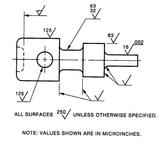
Requirements for surface finish are frequently found on technical drawings for mechanical parts particularly where parts fit together tightly move against each other or form a seal. The technical engineering drawing abbreviations we outline here are the terms used in the manufacturing and inspection of parts and assemblies. The Symbol indicates that all of the component surfaces are to be machined.
The pictorial representation using these symbols is defined in ISO 13022002. They are listed below. The surface roughness is generally indicated with the symbol and displays information including surface roughness value cutoff value machining method sampling length surface waviness and crease direction symbol as below.
You can find the list of common engineering drawing abbreviations. When you search for machining surface finish symbols on your favorite browser you would notice a range of abbreviations. Ra and D are two important surface finish parameters The Surface Finish Units we would use for parameters like Ra would be either micro-inches English or Imperial or micrometers Metric.
Y the vertical deviation from nominal surface. Surface Roughness Chart Symbols and Abbreviations. This section will explain how to write these symbols to indicate surface textures.
The Symbol indicates the surface finish requirements and shows a machining allowance requirement of 3mm on all surfaces. Maximum waviness spacing roughness sampling length e lay symbol maximum waviness spacing rating c. Arithmetic Average AA Ra arithmetic mean value of roughness.
Are indicated around the surface symbol as shown in Fig.

Solved Iso Surface Roughness Symbol Missing Roughness Autodesk Community
Complete Surface Finish Chart Symbols Roughness Conversion Tables
Surface Finish Texture Symbols Drafting Gd T Simpliengineering

Surface Finish Wikipedia
Complete Surface Finish Chart Symbols Roughness Conversion Tables
Iso Surface Roughness Symbols Terminology
Surface Finish Surface Roughness It S Indications Symbols
Surface Roughness Symbol In Drawings Mechanical Engineering General Discussion Eng Tips
0 comments
Post a Comment